JHY PCB Blog Hub

Your Source for Expert PCB Design, Manufacturing, and Assembly Insights – Stay Informed with 2025 Trends!

Why Choose a 35kV Power Transformer?

Choosing a 35kv Power Transformer is a practical decision about safety, reliability, and long-term operating cost. It is not simply a matter of selecting a larger nameplate. The transformer must match the network voltage, load profile, fault level, cooling method, and installation environment.

John J. Winders Jr., a recognized transformer engineering author, defines the device clearly: “A transformer is a static electrical device that transfers electrical energy from one circuit to another circuit without a change in frequency.” This principle explains why medium-voltage systems depend on careful transformer selection. A properly designed 35kv Power Transformer can reduce transmission losses, support stable distribution, and provide dependable power for factories, substations, renewable-energy facilities, and infrastructure projects.

The details matter. A dusty site may require stronger enclosure protection. A fluctuating industrial load may need additional thermal capacity. Coastal installations can demand improved corrosion resistance. No rating solves poor planning. Engineers should also review insulation coordination, short-circuit withstand, oil or dry-type construction, maintenance access, and future expansion.

There is room for caution. A transformer that performs well in a test room may behave differently under heat, harmonics, or uneven loading. That gap deserves attention. The best choice combines verified test data, field experience, manufacturer support, and transparent lifecycle calculations. Performance today is important. Adaptability tomorrow may matter more.
Why Choose a 35kV Power Transformer?

35kV Power Transformers: Definition and Typical Applications

Why Choose a 35kV Power Transformer?

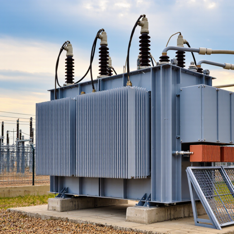
A 35kV power transformer changes electrical voltage between transmission, subtransmission, and distribution networks. It commonly receives medium-high voltage and reduces it for industrial equipment or local distribution. Some installations also use it to raise generated power before grid connection. These transformers may be oil-immersed or dry-type, depending on space, fire protection, cooling, and maintenance requirements.

Typical applications include utility substations, renewable energy collection systems, factories, mines, and large commercial facilities. In a substation, a 35kV transformer can supply several outgoing feeders while maintaining stable voltage under changing loads. In a solar or wind project, it gathers power from multiple inverters and transfers it toward the grid. Correct sizing depends on rated power, impedance, insulation level, cooling method, ambient temperature, and expected load growth. A 35kV rating alone does not guarantee suitability.

Experience shows that installation details often decide long-term reliability. Engineers should check cable clearances, grounding paths, protection coordination, noise limits, and access for testing. One early load estimate may be wrong. Revisit it.

Tips: Confirm the utility’s voltage requirements before ordering. Review short-circuit withstand data and routine test reports. Keep ventilation paths clear. Record oil temperature, moisture indicators, and unusual noise during inspections. Small changes can reveal larger problems, but inspection records should support every decision.

Why Choose a 35kV Power Transformer? - 35kV Power Transformers: Definition and Typical Applications

Data Dimension Typical Data or Description Why It Matters
Definition A power transformer designed for medium-voltage systems with a nominal voltage of approximately 35 kV. It transfers electrical energy between voltage levels while maintaining the same frequency.
Common Equipment Voltage Class 40.5 kV maximum system-voltage class is commonly used for equipment connected to 35 kV networks. The higher equipment rating provides insulation and operating margin above the nominal network voltage.
Typical Voltage Ratio Examples include 35/10 kV, 35/6.3 kV, 35/0.4 kV, and 35/11 kV, depending on the distribution system. The ratio is selected to match the utility network, industrial load, or renewable-energy collection system.
Typical Rated Power Common project ratings range from about 1 MVA to 63 MVA; larger ratings may be available for specific substations. The required MVA rating should account for present demand, motor starting, harmonics, and planned load growth.
Frequency 50 Hz or 60 Hz, according to the local power system. Frequency affects the magnetic design, losses, impedance, and compatibility with the connected network.
Transformer Type Oil-immersed transformers are common for outdoor substations; cast-resin or dry-type designs are used where fire safety or indoor installation is important. The construction type influences fire risk, maintenance, installation space, environmental protection, and total cost.
Cooling Method ONAN cooling is widely used for oil-immersed units; larger transformers may use ONAF cooling with fans. Cooling capacity determines the continuous load capability and helps control insulation aging.
Tap-Changer Arrangement An off-circuit tap changer is common; an on-load tap changer may be specified when voltage regulation is required during operation. Tap adjustment helps compensate for network-voltage variation and maintain an appropriate secondary voltage.
Typical Applications Utility distribution substations, industrial plants, mining sites, commercial facilities, data centers, and renewable-energy collection networks. A 35 kV level is suitable for delivering substantial power over medium distances with lower current than low-voltage distribution.
Transmission Efficiency For the same transferred power, increasing voltage reduces current and therefore lowers conductor I²R losses. This can improve feeder efficiency and reduce the required conductor size compared with lower-voltage distribution.
Insulation Requirements The design includes phase-to-ground and phase-to-phase insulation suitable for the applicable 35 kV system and overvoltage conditions. Adequate insulation coordination protects the transformer against switching surges, lightning impulses, and temporary overvoltages.
Protection and Monitoring Typical devices include overcurrent and earth-fault protection, temperature monitoring, pressure relief, and, for oil-filled units, gas or oil-level monitoring. Protection systems detect abnormal conditions quickly and help limit equipment damage and service interruptions.
Applicable Standards Design and testing commonly reference IEC 60076 or equivalent national standards, together with local grid requirements. Standards define requirements for ratings, insulation, temperature rise, losses, routine tests, and type or special tests.
Primary Selection Factors Load profile, rated power, voltage ratio, short-circuit impedance, installation environment, cooling method, tap range, and future expansion. Correct specification improves reliability, energy efficiency, safety, maintainability, and lifecycle cost.

How 35kV Transformers Operate Within Medium-Voltage Networks

Why Choose a 35kV Power Transformer?

A 35kV transformer operates as a key interface in medium-voltage networks. It receives electricity from an incoming feeder and changes the voltage for local distribution or industrial equipment. Inside the tank, alternating current creates a magnetic field around the primary winding. This field induces voltage in the secondary winding. The turns ratio determines the final voltage level.

In practice, the transformer works with circuit breakers, relays, surge protection, and grounding equipment. These devices help isolate faults and reduce damage during short circuits or switching events. A tap changer can adjust output voltage when network conditions change. However, voltage regulation is not always smooth. Cable length, uneven loading, and sudden motor starts can still cause noticeable fluctuations.

Engineers should check temperature, oil condition, winding resistance, and load trends during scheduled inspections. Small warning signs matter.

Tips: Keep ventilation paths clear and record operating temperatures. Inspect bushings for cracks, contamination, or unusual noise. Do not rely on nameplate ratings alone. Actual loading, altitude, ambient heat, and harmonics affect transformer performance. Protection settings also require careful coordination with upstream and downstream equipment. A technically correct setting can still perform poorly if the network has changed. Engineers sometimes discover this too late. Regular testing and updated drawings make troubleshooting faster and safer.

Key Benefits of Selecting a 35kV Power Transformer

Why Choose a 35kV Power Transformer?

Key Benefits of Selecting a 35kV Power Transformer

A 35kV power transformer can reduce current on medium-voltage feeders. Lower current means lower I²R losses and smaller voltage drops. For example, a 10 MVA, three-phase load draws about 165 amperes at 35kV. At 11kV, it draws approximately 525 amperes. The theoretical current reduction is substantial. Real savings still depend on conductor length, loading, temperature, and network design.

Capacity is another practical benefit. A 35kV system can serve industrial plants, renewable-energy collection networks, and expanding utility corridors. It provides useful headroom when demand rises. The International Energy Agency’s Electricity Grids and Secure Energy Transitions report states that annual grid investment must exceed 600 billion dollars by 2030. Higher-voltage infrastructure can support that expansion with fewer high-current constraints. It is not a universal solution.

Reliability also depends on correct specification. Engineers must check insulation coordination, short-circuit withstand, cooling class, tap range, and local protection settings. IEC 60076 provides the main technical framework for power transformers. The U.S. Department of Energy’s Electric Grid Supply Chain Review identifies transformer availability and long procurement periods as serious planning concerns. A rushed specification may create delays. I would also question oversized designs; unused capacity increases capital cost and may reduce efficiency under light loads.

Why Choose a 35kV Power Transformer?

For a balanced three-phase 10 MVA load, increasing the transmission voltage reduces the current required to deliver the same apparent power. At 35kV, the calculated current is approximately 165A, compared with 262A at 22kV and 525A at 11kV. Lower current can reduce conductor losses and support more efficient, economical power transmission.

Calculation basis: I = S ÷ (√3 × V), where S = 10 MVA and V is the line-to-line voltage. Values are theoretical balanced-load calculations and exclude equipment losses.

Technical Factors for Choosing the Right 35kV Transformer

Choosing a 35kV power transformer requires more than matching the rated voltage. The first technical question is load behavior. Record peak demand, daily variation, motor starting current, and future expansion. A transformer sized only for today may overheat tomorrow. The IEA Electricity 2024 report projects global electricity demand to grow by about 3.2% annually from 2024 to 2026. That trend supports careful capacity planning.

Impedance also deserves close attention. Low impedance reduces voltage drop, but it can increase fault current. Protection settings must match the transformer and the connected network. Check insulation coordination, lightning impulse withstand, altitude, ambient temperature, and cooling conditions. IEC 60076 provides the main testing and performance framework.

However, compliance alone does not guarantee a suitable installation. Harmonic-producing drives can increase winding losses, while poor ventilation can shorten insulation life. This detail is often underestimated.

Tips: Compare the 35kV transformer’s loss data at realistic loading, not only at full rating. Request sound-level information for residential or hospital sites. Review tap-changer range against seasonal voltage changes. Include oil containment and fire planning. A slightly larger transformer may reduce future stress, but oversizing can increase no-load losses. That trade-off needs a real load study, not a guess. Always verify the manufacturer’s test records, temperature-rise results, and protection coordination before purchase.

Installation, Safety, and Maintenance Requirements for 35kV Systems

Why Choose a 35kV Power Transformer?

Installation, Safety, and Maintenance Requirements for 35kV Systems

A 35kV power transformer suits industrial facilities, utility substations, and large commercial networks. It transfers substantial power while reducing losses across long distribution routes. Yet voltage level alone does not guarantee a reliable installation. Site conditions matter.

Installation starts with a level foundation, suitable drainage, and enough working space. The foundation must support the transformer, accessories, and possible vibration. Engineers should verify cable routes, phase clearances, ventilation, and grounding before delivery. Indoor rooms need controlled temperature and airflow. Outdoor units need protection from flooding, dust, and unauthorized access. Keep access routes clear.

Before energization, qualified personnel should inspect connections, insulation resistance, winding resistance, and protective devices. A second person should review the test records. Small errors matter. Safety depends on isolation procedures, visible grounding, barriers, and correctly rated protective equipment. Arc-flash boundaries must be marked and respected. Grounding conductors require secure, corrosion-resistant connections. Never rely on warning labels alone.

Maintenance should follow the duty cycle and site environment. Inspect bushings, terminals, seals, radiators, and cooling fans for damage or overheating. Thermal scans can reveal loose connections before failure occurs. Oil-filled units may require oil quality testing and dissolved gas analysis. Keep test results with repair histories and operating readings. No checklist is perfect. Missed labels or incomplete records can delay a repair. Applicable electrical codes, utility rules, and current engineering standards should guide every decision.

Scroll to Top